Short guides for purchasing and design engineers: forging ratio, heat treatment conditions, ultrasonic testing classes, machining allowance and an English–Turkish glossary.
01
What is open-die forging?
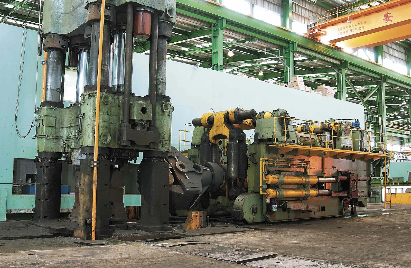
In open-die forging, hot steel is pressed between flat or V-shaped dies that never fully enclose the workpiece. After each stroke the part is turned and advanced by a manipulator. The same dies can therefore produce a wide range of diameters and lengths.
There are three basic operations:
Drawing out: The cross-section is reduced and the length increased. Shafts and bars are made this way.
Upsetting: The length is reduced and the cross-section increased. Discs and gear blanks are made this way.
Piercing: A hole is punched through the centre of an upset disc. Used for rings and sleeves.
Because there is no die cost, single parts and small series are economical. For large sections and heavy parts (from a few tonnes to several tens of tonnes) it is the only practical forging method.
02
Forging ratio (reduction ratio)
The forging ratio is the cross-sectional area of the ingot before forging divided by the cross-sectional area after forging:
Forging ratio = Aingot / Apart
Example: if a Ø516 mm shaft is forged from a Ø900 mm ingot, the ratio is (900 / 516)² ≈ 3.0 : 1.
Porosity and voids that form in the centre of the ingot during casting are closed by sufficient forging reduction. The coarse as-cast structure also becomes a fine-grained, directionally aligned structure. In practice, a ratio of at least 3:1 is often required for shafts. For critical parts (turbines, ship shafts) specifications may call for 4:1 or more. For discs forged by upsetting, the upsetting ratio (initial height / final thickness) is stated separately.
State the minimum forging ratio in your order. You can ask for it to be recorded on the inspection certificate.
03
Forging, casting or rolled bar?
Open-die forging
Casting
Rolled bar
Internal structure
Dense, void-free, aligned grain flow
Risk of porosity and segregation
Dense; the core may be weaker at large diameters
Toughness / fatigue
Highest
Low
Good (at small diameters)
Size range
Ø150 – Ø1,200 mm and above
Almost unlimited shapes
Generally up to Ø300 mm
Complex shapes
Limited; machining required
Very good
None
Single piece / small series
Economical (no dies)
Pattern cost applies
From stock, cheapest
Typical use
Heavy shafts, gears, die blocks
Housings, frames, pump casings
Small shafts, bolts
04
Heat treatment conditions
The delivery condition stated in the order determines the hardness and structure in which the part arrives at your workshop. The abbreviations used in EN standards are:
+N · Normalised
Heating above Ac3 and cooling in air. Refines and homogenises the grain structure. A common delivery condition for carbon steels.
+QT · Quenched and tempered
Quenching in water or oil followed by tempering. Gives high strength together with toughness. Shafts and axles are usually ordered in this condition; strength decreases as the section increases.
+A · Soft annealed
Lowest hardness and best machinability. Chosen when the part will be hardened later at your end.
+FP · Ferrite-pearlite annealed
Preferred for case-hardening steels for good machinability and low distortion after carburising.
Pre-hardened
280–330 HB for plastic mould steels (1.2311, 1.2738). The mould is machined at this hardness and no further hardening is needed.
EN 10228-3 defines ultrasonic testing of ferritic steel forgings. Acceptance criteria are given in four quality classes: 1 is the least stringent and 4 the most stringent. As the class increases, the smallest equivalent flaw size that is recorded and rejected becomes smaller.
Class 1–2: General machine parts, low-stress areas.
Class 3: A common choice for shafts, gears and most rotating parts.
Class 4: High-speed parts or parts that are critical for fatigue.
Testing is usually carried out on a peeled or rough-turned surface. Reliable results cannot be obtained on the forged scale. In the order, state the class, the scope of testing (full volume / specific zones) and the stage of testing (before / after heat treatment).
06
How is machining allowance determined?
A forged part is made oversize relative to the finished dimension. The allowance covers forging tolerance, scale and the decarburised layer, and distortion during heat treatment. If the allowance is too small, black (unmachined) surface remains. If it is too large, you pay for unnecessary steel and swarf.
Finished diameter
Total allowance on diameter
Total allowance on length
Ø150 – 250 mm
+8 – 12 mm
+20 – 30 mm
Ø250 – 400 mm
+10 – 16 mm
+25 – 40 mm
Ø400 – 600 mm
+14 – 20 mm
+30 – 50 mm
Ø600 – 900 mm
+18 – 26 mm
+40 – 60 mm
The table shows typical workshop values; the allowance is smaller for peeled deliveries. The exact allowance is set in the quotation according to the material, length-to-diameter ratio and heat treatment. The calculator uses a sample allowance.
07
Order checklist
To have your quotation prepared quickly and accurately, include the following in your order:
Technical drawing, or finished dimensions and tolerances
Steel grade and standard (e.g. 42CrMo4 · EN 10083-3)
Delivery condition (+N, +QT, +A…) and required hardness / strength
Delivery surface: as-forged, peeled, rough-turned
Minimum forging ratio
Ultrasonic testing class (EN 10228-3) and any other inspections
Mechanical testing: specimen location, orientation, test temperature
Certificate type: EN 10204 2.2, 3.1 or 3.2 (and the approving body)